
Cement Tanker Aeration System: Fluidization, Airflow & Residue Control
A cement tanker aeration system sends compressed air into the powder bed to loosen packed cement and help it move toward the discharge outlet. Good aeration supports steady flow, efficient final cleanout and less repeated residue.
At Panda Mech, we design the aeration system as part of the complete pneumatic unloading system. We match it with the tank shape, air source, discharge line and receiving silo instead of treating the fluidized bed as an isolated part.
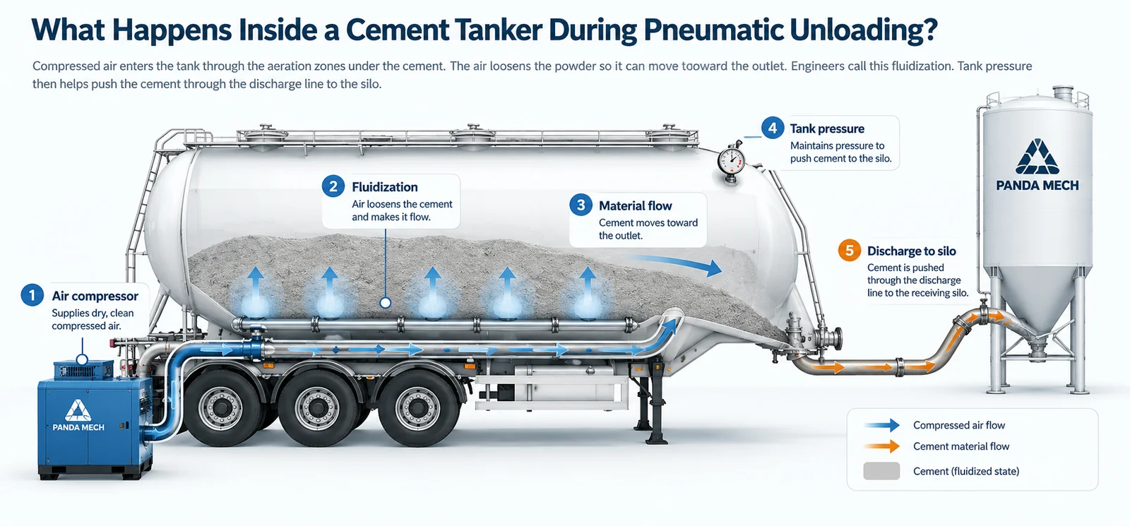
Airflow Starts Before the Fluidizing Bed
The compressor supplies the air, but compressor size alone does not decide unloading performance. Usable airflow must pass through the air lines and valves, reach the correct aeration zones and then move material through the discharge line.

The whole pneumatic path matters
Valves, piping, compressor output and the lower discharge structure all affect how much useful air reaches the cement.
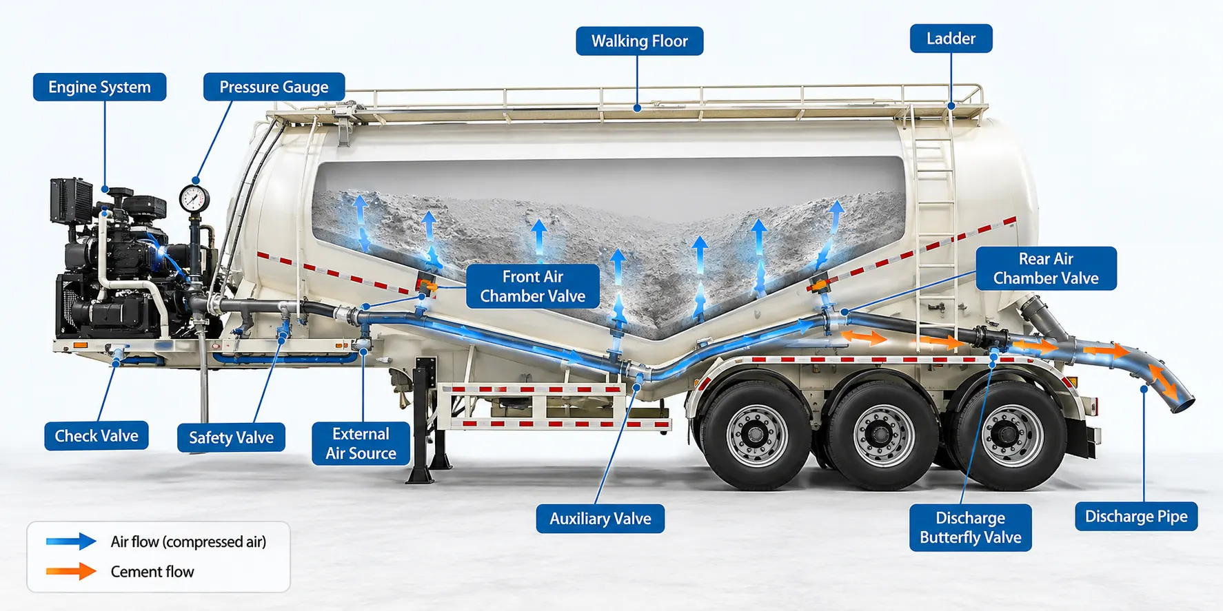
How a Cement Tanker Aeration System Works
Cement becomes packed during transport. During unloading, compressed air enters below the powder and passes through the fluidizing layer. This loosens the packed material so it can move toward the outlet.

Where the Air Goes During Pneumatic Unloading
The same air source can serve different jobs inside the unloading system. Knowing these jobs helps explain why more compressor output does not automatically mean faster cement flow.
| Air Function | What It Does | Why It Matters |
|---|---|---|
| Tank pressure air | Helps build the pressure needed for pneumatic discharge. | Too little usable air can make pressure build slowly or make unloading unstable. |
| Aeration air | Enters below the powder and loosens packed cement around the fluidizing area. | Poor aeration can leave cement packed, slow final cleanout or create repeated residue. |
| Secondary / conveying air | Helps material move through or clear the discharge line on applicable systems. | Poor air balance can cause pulsing flow or make the line difficult to clear. |
What Changes the Aeration System Setup?
Tank size alone does not decide the aeration setup. We also check the powder, tank shape, air source, discharge line and receiving site.
Cargo and Tank Conditions
- Cargo: cement, fly ash, lime and other mineral powders do not behave identically.
- Working bulk density: helps us match payload and tank volume correctly. It also affects how the powder behaves.
- Moisture and compaction: can make the powder cake together and harder to fluidize.
- Tank geometry: changes where the powder gathers and where aeration is needed.
Air Source and Receiving Site
- Air source: sets how much usable airflow the pneumatic system has.
- Line diameter and bends: change resistance inside the discharge line.
- Horizontal distance and vertical lift: make the unloading job harder as they increase.
- Silo backpressure and filter capacity: can slow unloading even when the tanker is working correctly.
Main Components of a Cement Tanker Aeration System
| Component | What We Check | Why It Matters |
|---|---|---|
| Air compressor / blower | Match usable airflow to the unloading job and the selected tanker setup. | Too little usable airflow can slow pressure build-up and weaken fluidization. |
| Air manifold and lines | Send air to the required zones while reducing leaks and blocked flow. | A good compressor cannot help if air leaks out or is blocked before it reaches the tank. |
| Aeration chambers / zones | Where the tanker uses separate zones, direct air to different parts of the tank during unloading and final cleanout. | Zone control helps when powder does not move evenly or stays in one part of the tank. |
| Fluidizing layer / bed | Spread air evenly enough through the powder. | Blockage, moisture or damage can weaken fluidization and leave repeated residue. |
| Tank geometry and outlet | Guide the loosened powder toward the outlet and reduce areas where material can stay trapped. | Good aeration cannot fully overcome a blocked outlet or a tank shape that does not guide powder well. |
| Secondary / boost air | Help clear the line or move material, depending on the exact pneumatic-system design. | Poor air balance can make material flow unstable or make the line hard to clear. |
Different Aeration Hardware You May See on Dry Bulk Tankers
Not every pneumatic dry-bulk tanker uses the same aeration hardware. The names below describe common industry concepts, not one fixed Panda Mech specification.
| Aeration Type | Plain-English Explanation | What Matters |
|---|---|---|
| Fluidizing bed / layer | A larger porous surface that spreads air below the powder. | Even airflow, media condition, sealing and service access. |
| Aeration chamber | An air space below or behind the fluidizing layer. | Leakage, contamination and how evenly the chamber feeds the fluidizing area. |
| Aeration zone | A tank section that can receive controlled airflow during unloading or cleanout. | Zone location, valve control and tank geometry. |
| Local aerator / air pad | A smaller local point that introduces air into powder on some hopper-style dry-bulk systems. | Position, blockage, sealing and access for inspection. |
| Multi-port aerator assembly | A local aerator housing with multiple air connections on some dry-bulk designs. | Compatibility with the actual trailer design, airflow path and sealing. |
Why Tank Shape and Aeration Must Work Together
Tank shape changes where powder gathers and how it moves toward the outlet. We therefore match the aeration layout to the actual tank geometry instead of copying one layout across every model.

V-Type Tank Geometry
The tank shape guides material toward its discharge area. Aeration needs to support that material path and final cleanout.
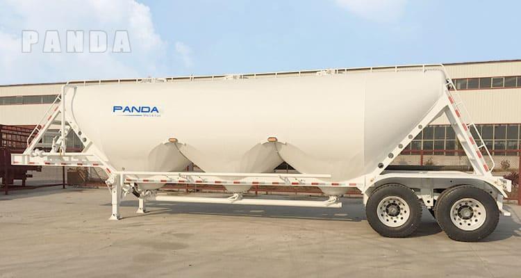
W-Type Tank Geometry
Multiple lower sections create different material-convergence zones, so the air-distribution and cleanout logic must match the design.
Cement Tanker Aeration Troubleshooting: Symptom → Cause → First Check
Slow unloading does not always mean the aeration system has failed. We first separate air-supply, leakage, cargo, aeration, discharge-line and receiving-silo causes before changing parts or pressure.
| What You See | Possible Cause | What We Check First | What It Means |
|---|---|---|---|
| Pressure builds but cement flow stays weak | Restriction or poor fluidization | Aeration zones → outlet → pipeline → receiving silo | The system may be using pressure to fight a restriction instead of moving cement. |
| Pressure will not build | Air leakage or insufficient usable airflow | Manhole sealing → valves → air lines → compressor output | Air may be leaking out or not reaching the tank fast enough. |
| Good start, very slow finish | Local cleanout or zone-control issue | Where material remains → relevant aeration zone → fluidizing layer | Main unloading may be normal, but the final cleanout is too slow. |
| Product flow pulses | Air/material imbalance | Zone valves → secondary air → hose/pipe restriction → cargo condition | The material flow is not steady. |
| The same area repeatedly retains cement | Local aeration or geometry issue | Fluidizing media → chamber below that area → internal flow path | The repeated residue location gives us a useful clue about the cause. |
| The trailer unloads normally at one site but slowly at another | Receiving-system or pipeline difference | Silo vent/filter → backpressure → line length → vertical lift → bends | The tanker may be working correctly, but the receiving site may be adding too much resistance. |
What Does >1.5 t/min Actually Mean?
Keep Cement Dry and Able to Flow
Moisture can make cement cake together, block airflow through the fluidizing layer and create buildup near the outlet or discharge line.
- Before loading: keep the tank and sealing areas suitable for dry-powder service.
- During unloading: watch pressure and product flow together.
- After unloading: note where residue remains before cleaning it away.
These units measure different things, so we do not convert one directly into the other or promise one fixed unloading time without the real site conditions.
Cement Tanker Aeration vs Cement Silo Aeration
Both systems use air to help dry powder flow, but they work in different equipment and solve different engineering problems.
| Point | Cement Tanker Aeration | Cement Silo Aeration |
|---|---|---|
| Where it works | Mobile pneumatic tanker | Stationary cement silo |
| Main job | Help cement move toward the tanker discharge outlet and support final cleanout | Help stored cement move near the silo cone or outlet |
| Works with | Tank pressure, air source, trailer discharge line and receiving conditions | Silo cone, plant air/blower system and downstream discharge equipment |
| Main engineering concern | Stable unloading, line resistance and tanker residue | Stored-material flow and silo outlet discharge |
How We Check the Pneumatic System Before Delivery
Good aeration also depends on correct manufacturing and final inspection. We check more than the fluidizing layer; the air source, lines, valves and discharge path must work as one system.
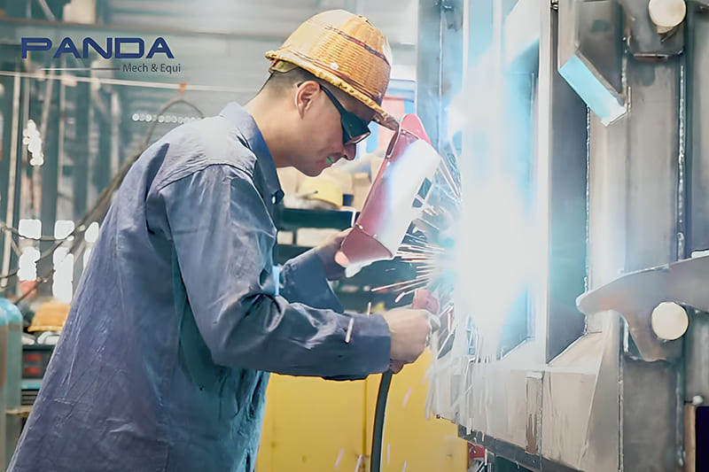
Air Line and Valve Leak Check
We check the air lines, connections and valves for leaks or installation problems that could reduce usable airflow.
Compressor and Engine Function Check
We check that the selected air-source system works correctly with the approved tanker setup.
Pressure and System Check
We complete pressure-related checks under the approved production and inspection procedure for that tanker setup.
Discharge System Check
Before shipment, we check the air source, air lines, valves and discharge path as one system.
What to Inspect When Unloading Performance Changes
| Inspection Area | Look For | Why It Matters |
|---|---|---|
| Fluidizing layer | Blocked areas, moisture, tears, loosened fixing or abnormal wear | Blocked or uneven areas change how air passes through the fluidizing layer and reaches the powder. |
| Aeration chambers | Leakage, contamination or damaged internal connections | A chamber problem can affect only one part of the tanker. |
| Air manifold / valves | Leaks, restricted lines or incorrect valve operation | The compressor can work normally while too little air reaches the correct zone. |
| Tank outlet | Hardened product, obstruction or repeated buildup | A blocked or restricted outlet can slow unloading even when fluidization is good. |
| Pressure instruments | Damage, blocked connection or implausible readings | If the pressure reading is wrong, it becomes much harder to find the real cause. |
What Should Be Easy to Inspect and Service?
A good pneumatic system should not only work when new. The parts most likely to affect airflow, pressure readings and cleanout should remain practical to inspect and service.
How Aeration Zones Help Final Cleanout
Some Panda Mech tanker setups use separate aeration zones. During final cleanout, the operator can direct air to different parts of the tank. If cement remains in one area, that zone can be checked instead of treating the whole tank as one chamber.
5 Aeration-System Mistakes to Avoid
- Choosing the compressor by power rating alone. Power or nominal air output does not show whether usable air reaches the powder correctly.
- Ignoring the receiving silo. Poor venting, filter restriction or high backpressure can make a correctly configured tanker unload slowly.
- Accepting “fluidized bed included” as a complete specification. You also need to know how air is spread, how zones are controlled and how the system is serviced.
- Increasing pressure whenever unloading slows. Higher pressure does not repair leakage, damp cargo, blocked fluidizing media, a restricted line or silo backpressure.
- Looking only at the start of unloading. Main discharge can look normal while final cleanout still takes too long.
Cement Tanker Aeration System FAQ
What is a cement tanker aeration system?
It is the part of the pneumatic unloading system that sends compressed air under or through the powder bed. The air loosens packed cement so it can move toward the discharge outlet.
How does a cement tanker fluidized bed work?
Compressed air passes through the fluidizing layer and into the packed powder. This loosens the particles and helps cement move toward the outlet for pneumatic conveying.
What is the difference between aeration air and conveying air?
Aeration air mainly loosens packed powder around the fluidizing area. Secondary or conveying air helps material move through or clear the discharge line on applicable systems. The exact air path depends on the tanker configuration.
Why can tanker pressure be high while cement flow is slow?
High pressure can mean the system is fighting resistance instead of moving cement efficiently. We first check the aeration zones, outlet, discharge line, cargo and receiving-silo backpressure before changing pressure.
What do bridging and rat-holing mean?
Bridging means powder forms a stable arch and stops falling toward the outlet. Rat-holing means material moves through a narrow channel while powder remains around that path.
Does a larger compressor always improve unloading?
No. Compressor output must match the aeration system and discharge line. Distance, vertical lift, bends, cargo behavior and silo conditions also matter. More nominal airflow will not fix a blocked or poorly distributed system.
Is cement tanker aeration the same as cement silo aeration?
No. Tanker aeration helps cement move out of a mobile pneumatic tanker. Silo aeration helps stored cement flow near a stationary silo outlet. The same basic fluidization idea may be used, but the equipment and engineering duty are different.
Why does cement remain inside the tanker after unloading?
Repeated residue can come from weak local aeration, blocked fluidizing media, moisture, poor cleanout steps or a restricted outlet. Tank shape and receiving-silo resistance can also be part of the problem.