
Check cement tanker ground clearance against the actual entrance profile, then check whether the route and unloading area can support the vehicle’s wheel loads and any loaded landing legs. Both checks must suit the planned tractor, trailer and cargo. A clearance figure or a “50-ton” model name alone cannot answer whether a tanker can use your site.
Start with the lowest parts of the coupled vehicle, the sharpest changes in road level, and the loads reaching each support point. This guide covers conventional pneumatic cement tankers. A tanker that raises its body also needs its own tipping-space and stability checks.
How Should You Check Cement Tanker Ground Clearance?
Measure the lowest vulnerable points with the tanker coupled to the intended tractor in its planned loaded condition and normal travel setting. Then compare the complete vehicle with the route profile. Ground clearance is the gap beneath a component. Whether that component strikes the road also depends on where it sits between, ahead of, or behind the vehicle’s supports.
Measure the coupled tanker in its working condition
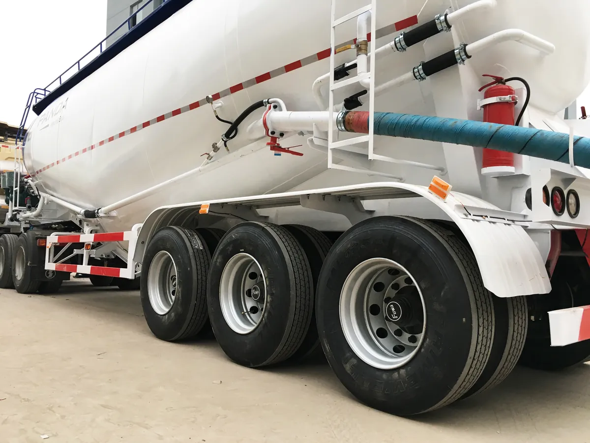
Begin with the vehicle drawing and a safe inspection on a firm, level surface. Record the tractor’s fifth-wheel height, trailer axle positions, tire sizes and suspension setting. The fifth wheel is the coupling plate that carries the front of the semi-trailer; its height changes the trailer’s attitude.
Inspect the tank’s lower fittings, discharge pipes and valves, fully retracted landing legs, and rear structure. The lowest point on one build may differ from another. Record each vulnerable point’s height and its position along the trailer, rather than reporting only the smallest gap.
Loading can change tire deflection and suspension position. Air suspension may maintain its set ride height, but that does not establish clearance for every component or road condition. Use the specified travel setting and the actual tire and suspension configuration. Measure from outside the vehicle where possible; never get beneath an unsupported vehicle.
JOST’s landing-gear instructions call for full retraction before travel and identify inadequate clearance as a cause of damage. Follow the instructions for the landing gear actually fitted to your trailer. Leaving a leg partly extended can turn an otherwise usable entrance into a collision point.
Check the whole vehicle over each change of slope
The change between slopes often matters more than the steepest slope itself. A long, smooth incline and a short, sharp ramp can have the same maximum gradient but very different effects on the underside.
- At a crest, the tractor and trailer supports can sit on opposite slopes while the road rises toward the underside. This is the breakover or high-centering problem.
- At a ramp entrance or exit, a low front fitting or rear overhang can strike as the vehicle changes angle. Overhang is the part extending beyond a support axle.
- Across ruts or a crossfall, one wheel path may be lower than the other. The resulting lean changes clearance on one side and affects vehicle stability.
Survey the route’s elevations and horizontal distances through each transition, including both wheel paths. Mark hump crests, drain channels, potholes, gates and turning points. During a turn, the trailer wheels track inside the tractor’s path, so the relevant surface may be an inner shoulder rather than the middle of the driveway.
Use these measurements with the actual tractor-trailer geometry to check the vehicle through successive positions. Include suspension movement, tire deflection and the site’s expected rutting in the agreed clearance allowance. FHWA route guidance highlights hang-up risks where low vehicles meet abrupt grade changes. Do not use a loaded tanker’s first arrival to discover whether a doubtful crest is passable. Repair the transition or agree another route before dispatch; reducing speed does not create missing geometric clearance.
What Loads Must the Yard Support?
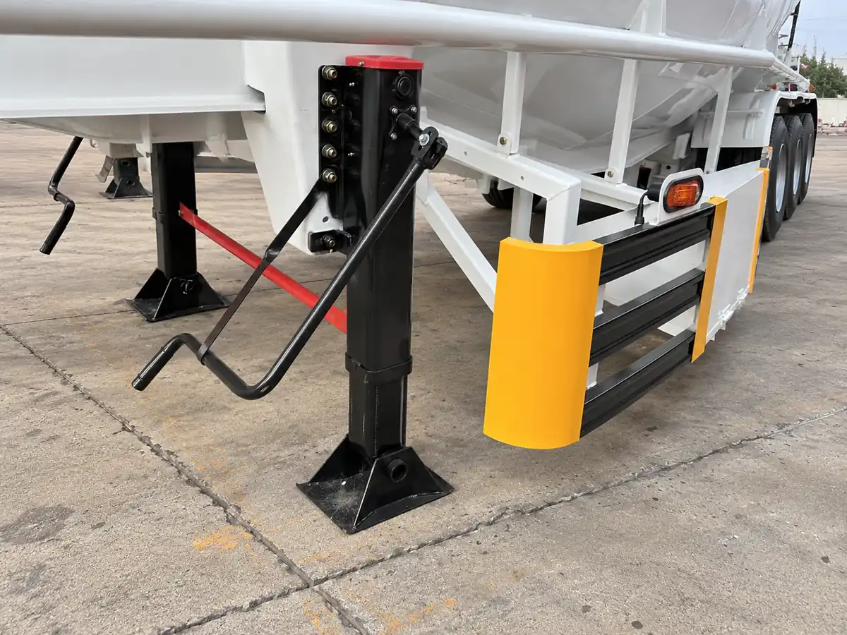
The yard must support the complete operating combination through its actual wheels and any loaded support legs. Cargo weight, total vehicle weight, axle load and ground contact pressure describe different parts of that job.
For arrival, include the tractor, empty trailer, cement and equipment carried on the vehicle. The empty vehicle weight is its tare. Obtain axle or axle-group weights for the planned loading arrangement, not just a total weighbridge ticket. The tractor carries part of the trailer load through the fifth wheel.
| Information to obtain | Where to get it | How it affects the site check |
|---|---|---|
| Loaded combination and axle/group weights | Loading records and suitable vehicle weighing | Establishes the loads the route will receive |
| Tire arrangement and axle spacing | Actual vehicle and approved drawing | Shows where neighboring wheel loads act together |
| Turning path and parking position | Site layout matched to the vehicle | Identifies loaded edges, shoulders, covers and joints |
| Delivery frequency and standing time | Transport schedule and unloading plan | Separates occasional access from repeated traffic and long stops |
| Landing-leg reactions, if used | Loading calculation for the supported trailer | Establishes the concentrated load beneath each leg |
At the surface, a tire transfers its load through a small contact area. Deeper in the pavement, the effects of neighboring tires and axles can overlap. TxDOT’s Pavement Manual explains why tire loads, wheel arrangements and load repetitions all matter. Adding an axle therefore requires a new load-distribution check; it does not automatically make a weak yard suitable.
Do not divide total vehicle weight by the rectangle occupied by the tanker. Most of that rectangle does not touch the ground. That average hides the wheel loads and support-leg loads that can damage a surface locally.
Also separate road permission from site suitability. A vehicle can meet the route’s legal weight limits while a drain cover, slab edge or recently filled trench remains too weak for its wheels. Check the tractor’s wheel paths as carefully as the trailer’s.
Is Concrete, Asphalt or Compacted Gravel Suitable?
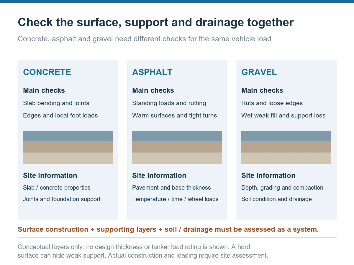
Any of these surfaces can form part of a suitable yard when its construction and underlying support match the loading. The material name alone does not establish capacity. A hard crust over weak fill can still settle, crack or rut under a cement tanker.
To assess whether a yard surface suits your cement tanker, check the whole structure: surface, base layers, supporting soil and drainage. The soil beneath the constructed layers is the subgrade. Its condition helps determine how the pavement behaves under load.
| Surface | What needs attention | Useful site information |
|---|---|---|
| Concrete | Slab bending, joints, unsupported edges, cracks and local loads beneath feet | Slab thickness, concrete properties, joint/load-transfer details, foundation support and damage records |
| Asphalt | Rutting or indentation during standing, temperature effects and stresses during tight turns | Pavement and base thickness, material condition, expected temperature, wheel loads and stopping time |
| Compacted gravel | Rutting, loose edges, weak fill and loss of support when wet | Layer depth, material grading, compaction records, soil condition and drainage |
For concrete, a compressive-strength value alone is not a vehicle-load rating. Slab thickness, support, load position and joint behavior also matter. ACI’s guide to industrial and trucking-facility paving explains the importance of uniform support and the damage associated with wet, weak soils or loss of support near joints.
For an asphalt standing area, include how long the tanker remains in one position. A surface that carries moving traffic may behave differently under prolonged concentrated loading, especially when warm. For gravel, check the prepared layers and the soil below them. Spreading loose stone over soft fill does not remove the weak layer.
Review the entire wheel path after heavy rain, drainage failures or utility work. Standing water, fresh settlement, deepening ruts, loose shoulders and water or fines emerging at slab joints are reasons to stop and investigate the affected area. Keep wheels away from unverified covers, buried services and excavation edges. HSE’s workplace transport guidance calls for firm, even, well-drained routes and firm, level unloading areas.
If the site report gives a California Bearing Ratio, or CBR, or a modulus of subgrade reaction, called a k-value, retain the original test conditions and units. These are pavement-design inputs. Neither is a ready-made allowable tanker weight or a ground-pressure limit in kPa. The site designer uses them with the pavement construction and loading information to assess the route.
How Do You Check Landing-Leg Ground Pressure?
For a trailer supported on landing legs, divide the load carried by each leg by its effective ground-contact area, then check the pad, pavement and supporting ground separately. Use the reaction at that leg: the force it transfers to the surface. Do not assume that two legs always share the front load equally.
First establish whether loaded uncoupling is permitted for the vehicle and operation. Obtain the support reactions for that loading arrangement, along with the landing-gear and mounting capacities. A landing-gear capacity label describes the equipment; it does not rate the ground beneath its feet.
For a fully supported pad, the average contact-pressure calculation is:
Average pressure q (kPa) = leg reaction R (kN) ÷ effective contact area A (m²). One kN/m² equals one kPa.
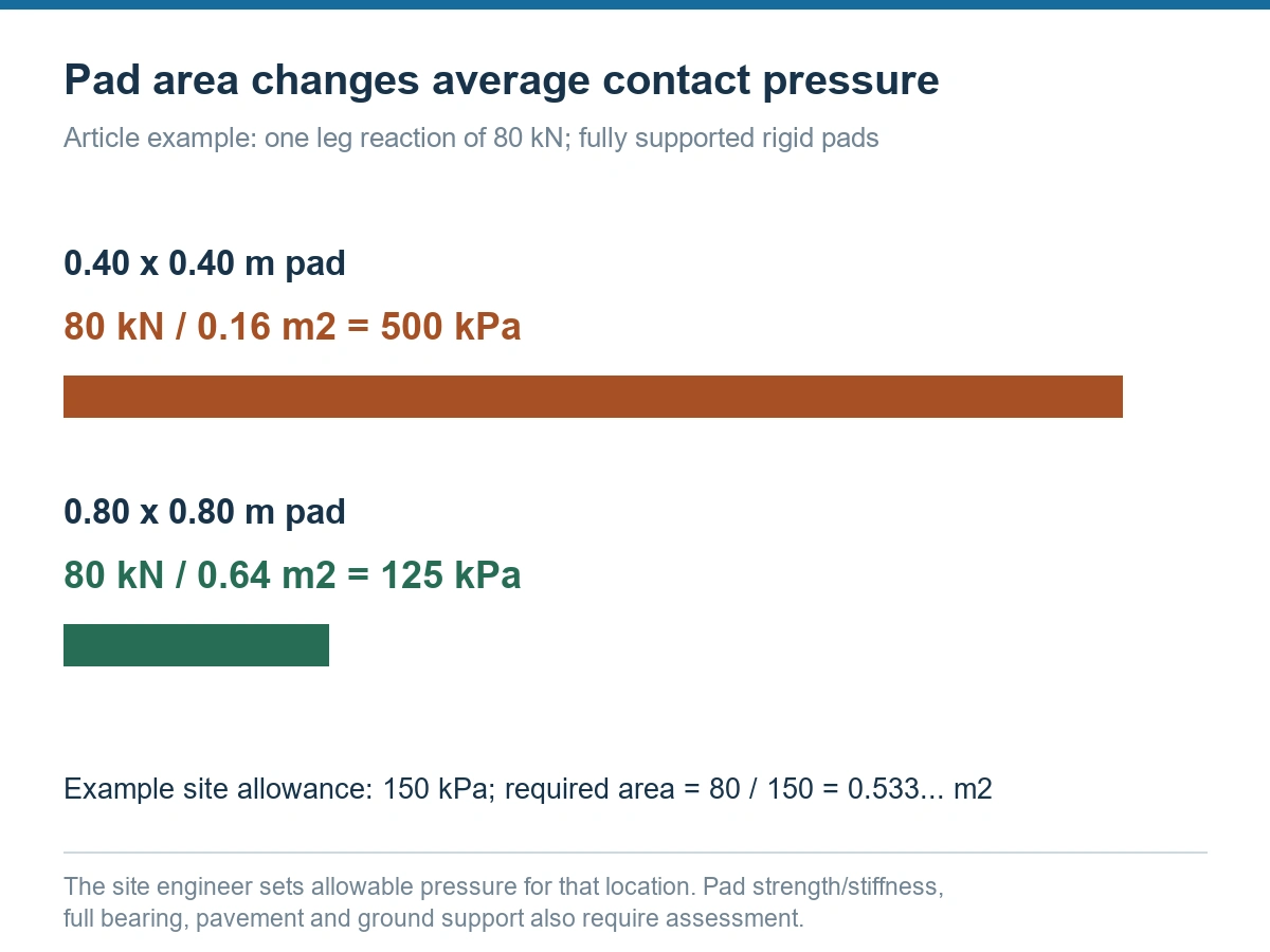
For example, suppose one leg carries 80 kN. Compare two rigid pads that each bear fully on a prepared, level surface:
| Pad dimensions | Effective contact area | Average pressure |
|---|---|---|
| 0.40 × 0.40 m | 0.16 m² | 80 ÷ 0.16 = 500 kPa |
| 0.80 × 0.80 m | 0.64 m² | 80 ÷ 0.64 = 125 kPa |
Suppose the site engineer has established an allowable pressure of 150 kPa for this prepared support location and loading condition. The area calculation gives 80 ÷ 150 = 0.533… m². The 0.64 m² pad satisfies that area comparison; the 0.16 m² pad does not.
The next checks are whether the pad can carry the concentrated foot load without excessive bending, whether the pavement can resist the local load, and whether settlement remains acceptable. Average pressure also hides uneven contact. A pad bridging a rut or touching only at one corner does not have its full outline area in effective contact.
Use R/A as a contact-pressure calculation, not as a concrete-thickness calculation. On a concrete slab, the load first acts on the slab, which bends and spreads it into the foundation. Local bearing and punching around a landing foot require their own assessment. A wider plate must have adequate stiffness and support; width alone does not complete the check.
What Should You Change When a Site Fails?
Correct the specific failed condition before sending the loaded vehicle. More ground clearance will not strengthen soft ground, and a stronger pavement will not remove a sharp crest that strikes the underside.
| Problem found | Preferred direction | What to check again |
|---|---|---|
| Pipe, leg or rear structure conflicts with a slope transition | Regrade the transition, use an engineered crossing arrangement, or change the route | Full vehicle geometry, wheel paths and remaining clearance |
| Soft fill, rutting, ponding or loss of pavement support | Correct drainage and repair or reconstruct the affected support layers; consider another unloading position | Ground condition, pavement structure and expected wheel loads |
| Planned axle loads exceed the route or site allowance | Revise the loading plan or vehicle arrangement; reduce cargo where this resolves the actual limit | New axle/group weights and the complete route |
| Landing feet overload the local support area | Use an approved support arrangement or avoid uncoupling at that location | Leg reactions, pad strength, pavement response and settlement |
A steel plate or temporary mat also needs a load and support check. It can distribute a load only as its strength, stiffness and bearing conditions allow. Placing a thin sheet across an unknown trench or soft patch can conceal the problem without providing adequate support.
Where another unloading position is available, compare it before changing the vehicle. A firm, level standing area with a gentler approach may remove both clearance and ground-support problems. Keep people separated from maneuvering vehicles and agree how any necessary reversing will be controlled.
Moving the tanker farther from the silo changes the discharge arrangement. Recheck hose distance, vertical lift, bends, connection and air-system requirements together. A safer parking position must also let the tanker discharge through a properly matched system; do not extend the hose without reviewing that change.
Agree the Route and Unloading Position Before Dispatch
Record the agreed vehicle, wheel paths, standing position and support arrangement before the first delivery. Then check that the site still matches that plan on arrival. New ruts, excavations, standing water or a moved unloading point can change the result.
Prepare these details for the vehicle and site teams:
- Vehicle and load: tractor model, fifth-wheel height, planned cargo, actual axle/group weights, tire arrangement and vehicle drawing.
- Access: entrance profile, transition measurements, turning space, both wheel paths, overhead obstructions and marked weak areas.
- Standing area: pavement and ground information, drainage condition, parking position, and whether the tractor remains coupled.
- Unloading: silo connection, hose route, distance, vertical lift and a protected working area for the driver.
For our 50 ton cement tanker trailer, discuss the intended tractor and site conditions before fixing the build. The model name is the starting product choice; the actual load distribution and vehicle geometry must match the job. We review the tractor, route and unloading arrangement when preparing the configuration and technical drawing.
Email the available vehicle details, site measurements and photos to [email protected]. Include your destination country and whether loaded uncoupling is planned. We can use these details for tanker configuration discussions; send the vehicle loads and wheel-path plan to the site’s civil or pavement engineer for the ground and pavement assessment.
Accept the delivery arrangement only when cement tanker ground clearance works along the agreed path and the site supports every loaded wheel or landing foot in the planned operating condition. Keep the route, load and unloading position together in the delivery instructions so a later change triggers the right recheck.
Frequently Asked Questions
I only have total weighbridge weight. Can I divide it by the trailer axle count?
No. The tractor carries part of the trailer load, and the trailer axles do not necessarily share their load equally. Obtain individual axle or axle-group weighing for the planned combination and loading arrangement. Label the results with the loading condition and identify the tire arrangement. If a ticket gives only a group total, retain that limitation and obtain the individual distribution needed for a local wheel-load check.
The yard is rated in tonnes per square metre. Is that enough?
A distributed-load rating does not, by itself, establish capacity for concentrated tire or landing-leg loads. Obtain the original design conditions, including the loaded area and support assumptions. Give the site engineer the axle loads, tire layout, wheel paths and any leg reactions. One tonne per square metre is about 9.81 kPa, but converting units does not turn a distributed-load allowance into a wheel-load rating.
An empty tanker clears the entrance. Does that prove a loaded tanker will clear it?
No. Recheck the intended loaded condition and normal travel setting before treating the entrance as suitable. Cargo can change tire deflection, suspension position and ground settlement. An air-suspension system that maintains ride height does not establish clearance for all fittings or prove the wheel paths can carry the loaded vehicle. Use the loaded geometry and site information to resolve the difference before arrival.
Do landing legs need checking if the tractor stays coupled?
If the legs carry no load during the planned operation, assess the tractor and trailer wheel loads for that arrangement. Check landing-leg reactions and local support when loaded uncoupling, tractor replacement or another leg-supported condition is planned. Do not lower the legs as extra supports unless that support arrangement is allowed by the vehicle instructions and has been assessed for the site.

ZAC
Hello, I’m ZAC, a cement trailer and semi-trailer specialist with over 20 years of industry experience. My technical approach starts with real operating conditions, including how cargo characteristics, road conditions, and loading and unloading methods affect trailer performance. I place particular emphasis on structural reliability, component compatibility, and ease of maintenance. I look at both everyday performance and how reliably a trailer operates over time, as well as how easily it can be inspected and serviced.


